
Product Description
As the SBR process operates in batch mode, it eliminates the need for secondary sedimentation tanks and sludge return systems, significantly reducing infrastructure investment while maintaining high treatment efficiency. The typical SBR operation cycle includes five phases: fill, react, settle, decant, and idle. The HLBS rotating decanter plays a vital role in the decant phase, ensuring regular and quantitative removal of treated water, which enables continuous wastewater treatment within the SBR basin.
Product Video
Watch the video below for a closer look at the HLBS Floating Decanter in action. It demonstrates the design features, operation process, and practical installation—ideal for understanding how the decanter integrates into your SBR system.
Working Principle
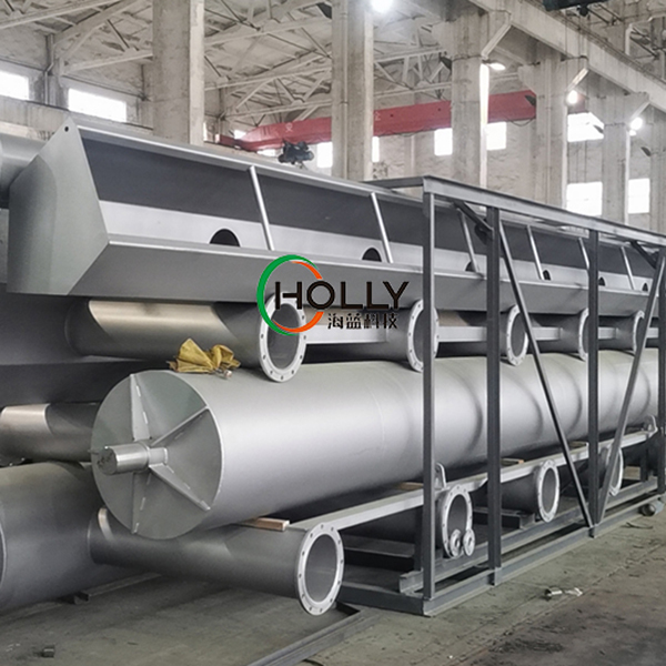
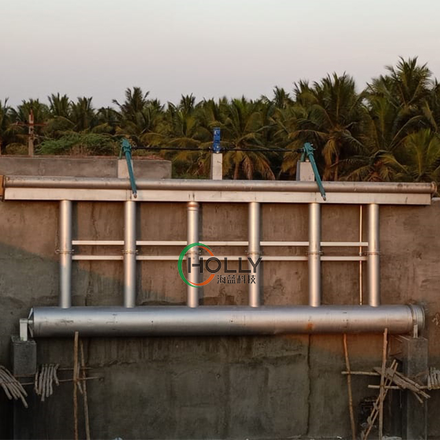
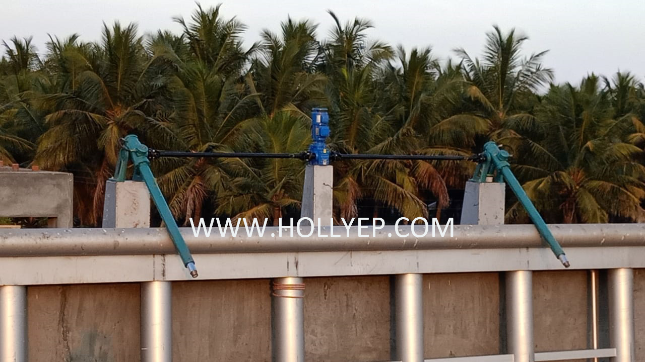
The HLBS Floating Decanter operates during the drainage phase of the SBR cycle. It is typically positioned at the maximum water level when idle.
Once activated, the decanting weir is gradually lowered by the transmission mechanism, initiating the decanting process. Water flows smoothly through the weir opening, supporting pipes, and main discharge pipe, and exits the tank in a controlled manner. When the weir reaches the predefined depth, the transmission mechanism reverses, swiftly raising the decanter back to the upper water level, ready for the next cycle.
This mechanism ensures accurate water level control, reduces turbulence, and prevents sludge resuspension.
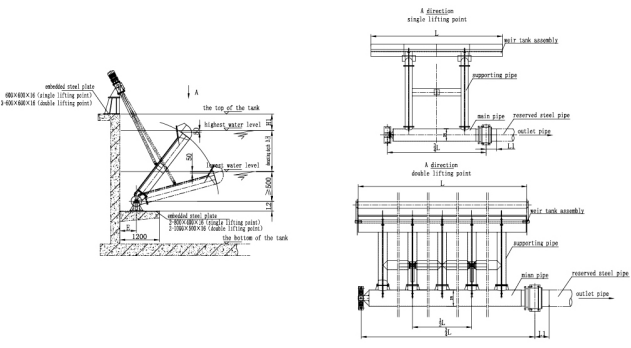
Installation Drawings
Below are schematic diagrams illustrating the installation layout of the HLBS Floating Decanter. These drawings offer useful reference for design planning and on-site implementation. Please contact us for customized installation support if needed.
Technical parameters
| Model | Capacity (m³/h) | Load of Weir Flow U (L/s) |
L(m) | L1(mm) | L2(mm) | DN(mm) | H(mm) | E(mm) |
| HLBS300 | 300 | 20-40 | 4 | 600 | 250 | 300 | 1.0 1.5 2.0 2.5 3.0 |
500 |
| HLBS400 | 400 | 5 | ||||||
| HLBS500 | 500 | 6 | 300 | 400 | ||||
| HLBS600 | 600 | 7 | ||||||
| HLBS700 | 700 | 9 | 800 | 350 | 700 | |||
| HLBS800 | 800 | 10 | 500 | |||||
| HLBS1000 | 1000 | 12 | 400 | |||||
| HLBS1200 | 1200 | 14 | ||||||
| HLBS1400 | 1400 | 16 | 500 | 600 | ||||
| HLBS1500 | 1500 | 17 | ||||||
| HLBS1600 | 1600 | 18 | ||||||
| HLBS1800 | 1800 | 20 | 600 | 650 | ||||
| HLBS2000 | 2000 | 22 | 700 |
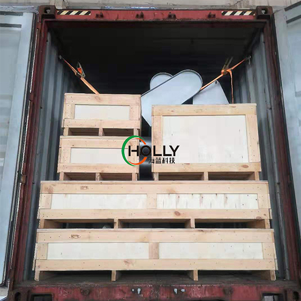
Packing & Delivery
The HLBS Floating Decanter is securely packed and shipped to ensure safe delivery. Our packaging complies with international logistics standards, ensuring product integrity throughout transportation.